Usage
Wiring
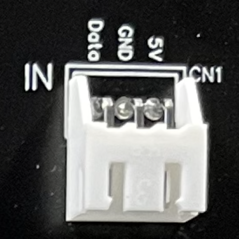
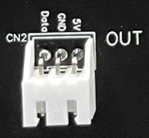
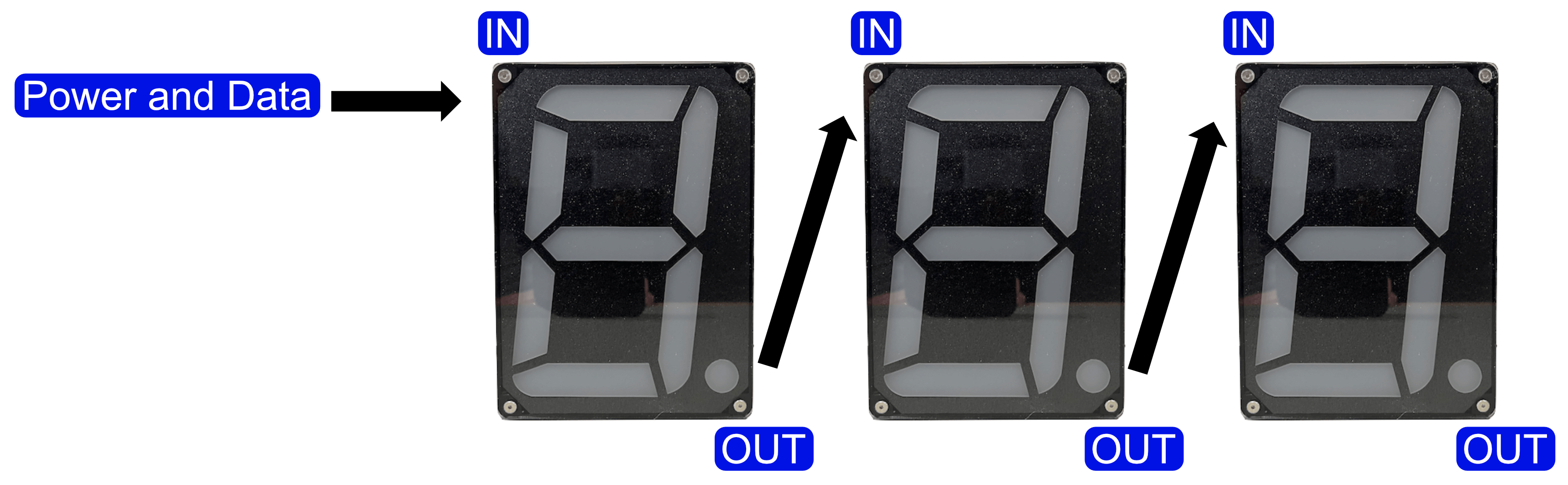
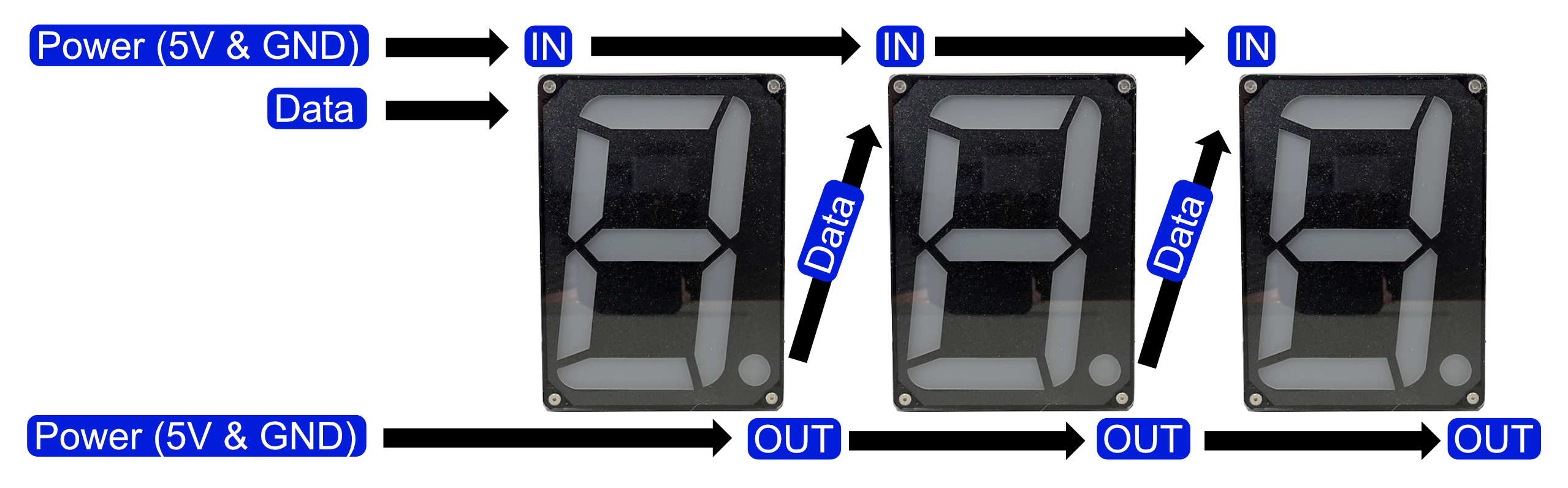
Sizable7 has two XH connectors, one for IN and one for OUT. Each connector has 3 contacts for 5V, GND and Data (just like any other WS2812 LED strip). Multiple Sizable7 modules can be chained together using the OUT from the first to the IN of the next.
You most likely need an external/separate 5V power source to power the module(s). Some people use the VIN pin of their ESP32 module to power external modules (most ESP32 modules have such a pin which will be at around 5V when connected to USB). This is not recommended for Sizable7 modules. The voltage and current rating of this pin will, most likely, not be sufficient to power a Sizable7. It can cause strange effects on the display or even reset the ESP32. So your wiring should look like this:
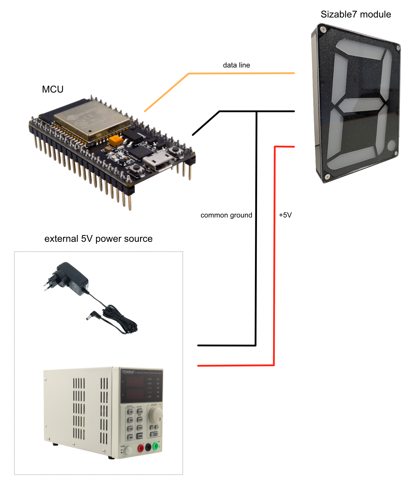
After you have wired up your Sizable7, you can use this example to test it.
Power distribution
For better power distribution (especially when having a longer chain) you could choose to tie all 5V and GND points together. That way the power is fed from multiple points. The 5V and GND on both connectors are at the same level and can be tied together without problems. The Data should be routed through the chain. Starting at the first IN connector and then from OUT to the next IN (with the last OUT unconnected).
It’s also good practice to add a capacitor (500–1000 µF at 6.3V or higher) between 5V and GND. Such a capacitor can buffer potential power fluctuations. See this excellent guide from Adafruit.
Coding
Sizable7 can be driven like any other LED strip using a micro controller like an ESP32. There are several libraries like FastLED to help you on your way. Sizable7 is like a regular LED strip, a chain of LED’s. The difference here is the layout of the pixels. There are 7 segments s0-s6 and 36 LED’s:
             s0

       00 01 02 03 04
    29                05
    28                06
s5  27                07  s1
    26       s6       08
    25                09
       30 31 32 33 34
    24                10
    23                11
s4  22                12  s2
    21                13
    20                14
       19 18 17 16 15     35

             s3
The following example Arduino sketch shows a way to map digits to segments/LED’s. It uses the FastLED library:
/*
    Sizable7 example sketch

    https://sizable7.nickstick.nl

*/

#include "FastLED.h"

#define DATA_PIN 4                      // GPIO data pin
#define S7_MODULES 4                    // number of Sizable7 modules in chain
#define NUM_LEDS S7_MODULES*36          // total number of LEDs

const uint8_t segmentLed[7][5] = {      // mapping of LEDs per segment
  {0,1,2,3,4},
  {5,6,7,8,9},
  {10,11,12,13,14},
  {15,16,17,18,19},
  {20,21,22,23,24},
  {25,26,27,28,29},
  {30,31,32,33,34}
};
const uint8_t digitSegment[10][7] = {   // mapping of segments per digit 0-9
  {0,1,2,3,4,5,99}, //0
  {1,2,99},         //1
  {0,1,6,4,3,99},   //2
  {0,1,6,2,3,99},   //3
  {5,6,1,2,99},     //4
  {0,5,6,2,3,99},   //5
  {0,5,6,4,2,3,99}, //6
  {0,1,2,99},       //7
  {0,1,2,3,4,5,6},  //8
  {0,1,5,6,2,3,99}  //9
};

CRGB leds[S7_MODULES*36];               // FastLED LEDs

void setDigit(CRGB leds[], uint8_t module, uint8_t digit, uint8_t h, uint8_t s, uint8_t v) {
  if ((module > S7_MODULES-1) || (digit > 9)) return;
  FastLED.clear(false);
  for(uint8_t segment = 0; segment < 7; segment++) {
    uint8_t onSegment = digitSegment[digit][segment];
    if (onSegment > 6) break;
    for(uint8_t led = 0; led < 5; led++) {
      leds[(segmentLed[onSegment][led])+(module*36)].setHSV(h, s, v);
    }
  }
}

void setup() {
  FastLED.addLeds<WS2812B, DATA_PIN, GRB>(leds, NUM_LEDS);
  FastLED.setMaxPowerInVoltsAndMilliamps(5,750*S7_MODULES);
  FastLED.clear(true);
}

void loop() {
  for(uint8_t color = 0; color < 256; color += 16) {
    for(uint8_t digit = 0; digit < 10; digit++) {
      setDigit(leds, 0, digit, color, 255, 255);
      FastLED.show();
      delay(200);
    }
  }
}
You also can use most animation examples that can be found (like the ones that ship with FastLED) but they need some minor modifications to map the LED’s in a way that looks nice. We have prepared a more interesting example for a clock with several animations and even a sound analyzer which shows patterns by analyzing ambient noise or music. You can watch a short video about it below (clock demo starts at around 50sec mark). You can read about the project in this post .